~ 10 min read
Enterprise Network Simulation of an Insurance Company
As part of my network engineering learning journey, I designed and implemented a mega lab in GNS3 simulating the infrastructure of a fictional company called Void Insurance Group.
Introduction
The objective of this project was to design a realistic enterprise architecture, prioritizing scalability, high availability, segmentation, and security.
The simulated company includes:
- 1 Headquarters (HQ)
- 4 branches of different sizes
- Centralized Data Center
- ISPs with different ASNs simulating the Internet
- PCs running Linux or Windows 7
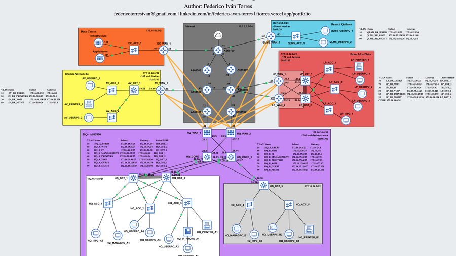
Network Architecture
The topology was structured under a hierarchical model:
- At the HQ, a Tier 3 architecture is used, with Core, Distribution, and Access layers, plus 2 WAN routers. If one WAN router fails, the other continues operating. In addition, the headquarters is divided into 2 subnets: Zone A, which has 2 distribution switches and multiple access switches, and Zone B with one distribution switch and access switches, considering that Zone B is smaller than Zone A.
- In large or medium branches, such as La Plata or Avellaneda, a Tier 2 (Collapsed Core) architecture plus WAN is used. The branch size determines the number of routers, switches, and other devices in the network.
- In smaller branches, such as Quilmes, only one switch connected to a WAN router is used due to the lower number of devices. In these cases, Router-on-a-Stick (ROAS) is implemented.
- In all cases, access layer switching is segmented using VLANs.
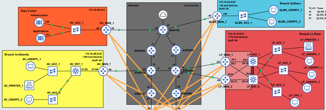 Enterprise Branches
Routing and WAN
OSPF
OSPF was used as the internal routing protocol, both for the corporate network and for the VPN tunnels between sites. For the tunnels, the point-to-point network type is used to avoid unnecessary OSPF traffic, which is not required in this case. The default gateway is advertised by the HQ WAN routers, so all traffic flows through them. Finally, the interfaces connected to the ISPs have OSPF messages disabled for security reasons (passive interface).
BGP
The HQ WAN routers exchange routes via BGP with the ISP routers to provide Internet connectivity, not only for the headquarters but also for the branches connected through IPsec. Additionally, the entire simulated Internet network uses BGP (eBGP) to exchange routes between the different ISPs (each with a different ASN).
Site-to-Site VPN
Branches connect securely to the HQ using a Site-to-Site VPN (GRE over IPsec tunnels), as confidentiality and integrity of corporate traffic are essential. IPsec profiles in transport mode are used, enabling encryption with AES, integrity with SHA-256, and authentication using a Pre-Shared Key (PSK). Each WAN router at every branch forms two tunnels with the HQ.
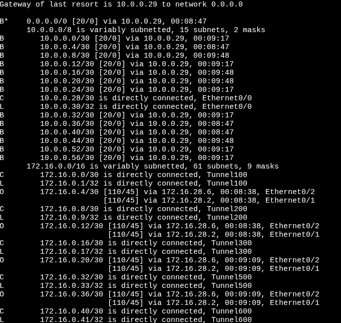 Top of the HQ_WAN_1 routing table
PAT
Port Address Translation (PAT) was implemented at the HQ WAN edge to allow internal networks to access the Internet. In this way, private IPv4 addresses are translated to the IP address of one of the HQ WAN routers. Therefore, even though the internal network is 172.16.0.0/16, packets originating from the HQ have the translated address 10.0.0.30 or 10.0.0.34.
High Availability
The HQ WAN routers are connected to two ISPs to ensure high availability. If one ISP fails, the other maintains connectivity. Additionally, HSRP is implemented at the distribution layer in the HQ and large branches. By using a virtual IP address, users remain connected to the network even if one of the distribution switches fails.
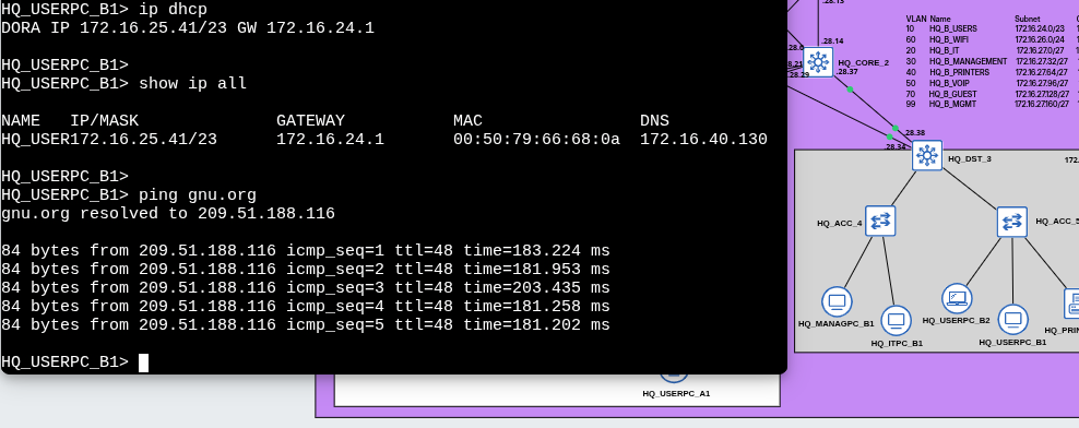
Due to the configuration of multiple protocols and services, the network may take approximately 5 minutes to reach full operational status. The process is as follows:
- BGP is initialized and synchronized between the WAN routers.
- GRE over IPsec tunnels are established between the branches and the headquarters.
- OSPF is initialized and converges between the internal enterprise routers.
- The Spanning Tree Protocol transitions the switches through the discarding -> learning -> forwarding states.
- End devices send DHCP requests to obtain a dynamic IP address.
- Once these processes are completed, network and Internet access become available.
 Network convergence process until Internet access is available
IP Addressing
The company’s internal network uses the 172.16.0.0/16 range, while the WAN uses the 10.0.0.0/8 range. Although private IP addresses are not routable over the Internet, external access is possible through the use of NAT (Network Address Translation).
Additionally, point-to-point connections between the ISPs and between the enterprise network and the ISPs use a /30 mask, optimizing IP address utilization.
Considering the company’s requirements, the segmentation using VLSM is defined as follows:
| Site | Staff | Devices | Subnet |
|---|---|---|---|
| HQ | 300 | ~700 | 172.16.16.0/19 |
| La Plata | 80 | ~170 | 172.16.32.0/21 |
| Avellaneda | 40 | ~100 | 172.16.48.0/22 |
| Quilmes | 20 | ~50 | 172.16.52.0/23 |
Internal Segmentation of the HQ
The headquarters (HQ) is subdivided into three zones:
- Zone A: 172.16.16.0/21
- Zone B: 172.16.24.0/22
- Core: 172.16.28.0/24
GRE over IPsec Tunnels
The GRE over IPsec tunnels use the reserved range 172.16.0.0/24. Each link uses a /30 mask, as they are point-to-point connections.
VLANs and IP Address Allocation
Within each site (or zone, in the case of HQ), an additional subdivision is performed using VLSM to create VLANs.
- VLANs with a larger number of users (such as WiFi or Users) are assigned subnets with greater capacity.
- VLANs with lower number os users (such as Voice or Management) use more restrictive subnet masks.
Besides SVI or ROAS configuration, IP address allocation per VLAN is primarily managed by the DHCP server located in the Data Center.
The DHCP server is configured so that:
- The first 8 IP addresses of each subnet are reserved for static assignments.
- In environments using HSRP:
- The first two IP addresses are assigned to the multilayer switch SVIs.
- The last usable address is reserved as the Virtual IP (default gateway for end devices).
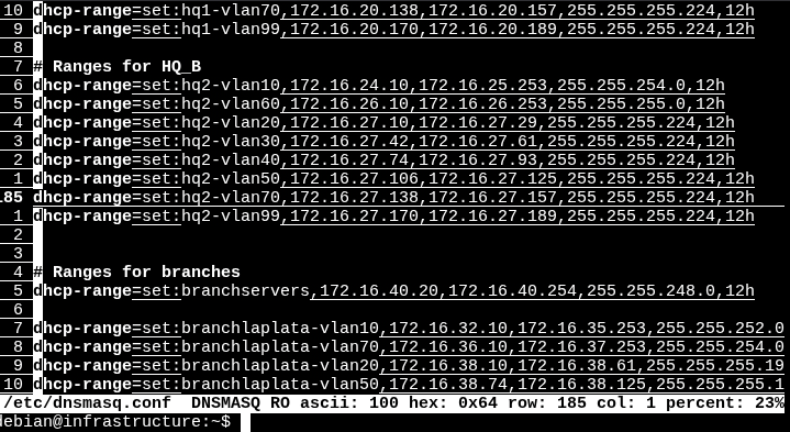 DHCP server configuration
Scalability
Each branch subnet maintains unused address space reserved for future expansion.
Additionally, the subnets 172.16.56.0/22 and 172.16.54.0/23 are available in case new branches need to be added to the network.
Switching and Layer 2
The headquarters network was segmented using multiple VLANs:
- Users
- IT
- Management
- Printers
- VoIP
- WiFi
- Guest
Smaller branches use fewer VLANs, prioritizing that certain VLANs, such as Users, have more available IP addresses than others. For example, if a branch has a block of 64 addresses, 32 are allocated to the Users VLAN and the remaining 32 are distributed between VoIP and Management.
Layer 2 Technologies
The distribution multilayer switches (L3 Switches) use EtherChannel to increase bandwidth between them. This is particularly important in high-traffic scenarios.
Spanning Tree was also tuned so that the root bridge matches the switch acting as the HSRP active device for each VLAN. In some VLANs, a switch may be both root bridge and HSRP active, while in others it may not be the root bridge and operate as HSRP standby.
Additionally, BPDU Guard and PortFast were implemented to improve stability and security at the access layer, always enabled on interfaces connecting to end-user devices.
Furthermore, DTP was disabled for security reasons, and VTP was configured so that distribution switches control the VLAN database. Distribution switches operate in server mode, while access switches operate in client mode.
Finally, Layer 2 attack prevention mechanisms were implemented:
- Port Security (Limits which devices (MAC addresses) can connect to a switch port).
- DHCP Snooping (Allows only trusted DHCP servers and blocks rogue responses).
- Dynamic ARP Inspection (Validates ARP messages to prevent spoofing).
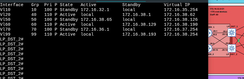 HSRP operating in La Plata branch
Segmentation and Security
The company may have a security policy that requires all devices to send their DNS requests exclusively to the internal DNS server. ACLs were implemented to prevent certain types of traffic from accessing specific subnets.
Additionally, Telnet was disabled on all devices and remote access was implemented using SSH, avoiding the use of serial console connections for configuration and administration. SSH access is also restricted to the internal corporate network.
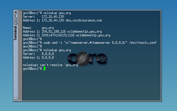 Devices can only send DNS requests to the internal server
Infrastructure Services
The centralized Data Center includes:
- An infrastructure server providing an internal DNS service (using dnsmasq). Additionally, it has a DHCP service running that provides per VLAN host configuration. Each subnet of every branch has its own address pool, default gateway, DNS server address, and domain name.
 DNS and DHCP
- A services server that runs SFTP (ftp) and HTTP (webpage) using sshd and httpd.
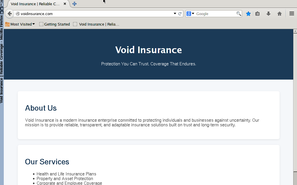 Enterprise internal webpage
Log Monitoring
Monitoring was centralized using Loki + Grafana to visualize logs on an external Raspberry Pi 4 outside the GNS3 network, simulating Grafana in the cloud.
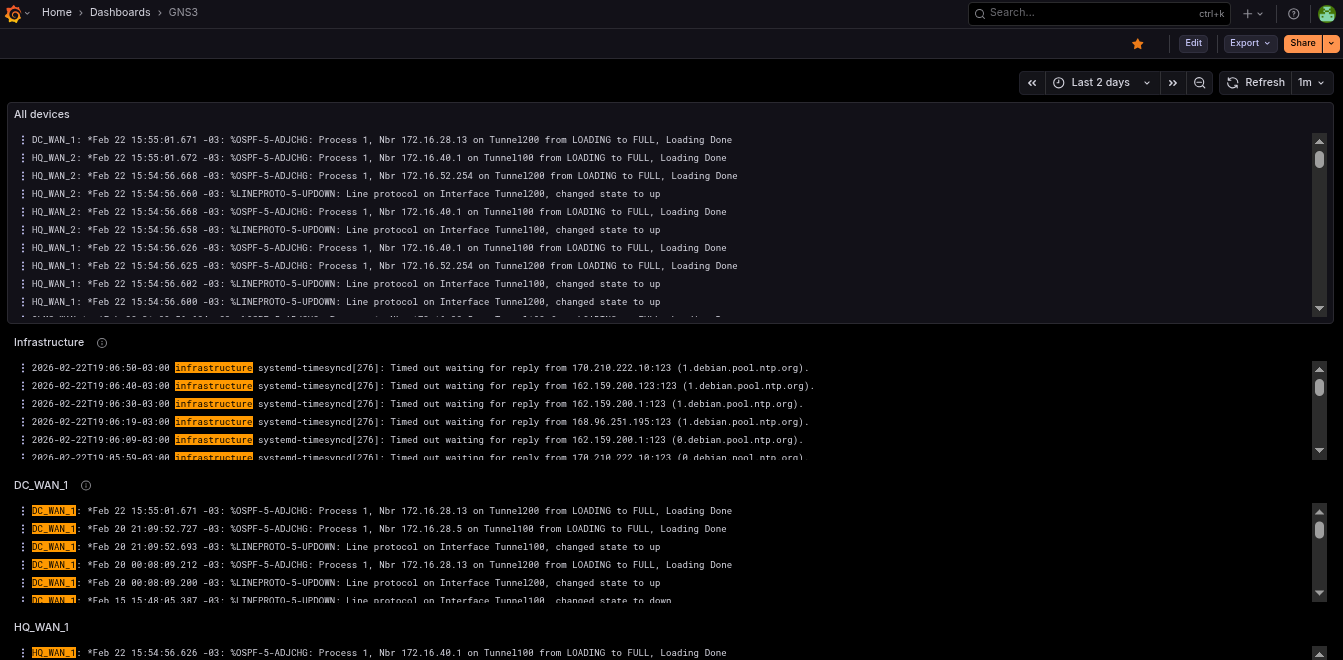 Log monitoring in Grafana using Loki and Prometheus
Devices send events to the Raspberry Pi 4 via Syslog. Each device also includes its hostname in the message to make filtering easier in the Grafana Loki dashboard.
Technical Challenges Encountered
During implementation, multiple technical challenges arose:
- Configuring DHCP for each VLAN in every branch. It was important to consider IP address ranges and reserve the default gateway address.
- I encountered issues configuring Loki with Grafana and Promtail. Errors in Promtail caused the server to fill with logs, making debugging more difficult. The biggest problem was discovering that the server firewall blocked Promtail data from reaching Grafana (even though everything was on
localhost). - On several occasions, OSPF did not form adjacencies over IPsec. After extensive troubleshooting, I discovered the problem was that the branches were not running BGP (which was intentional), so I added a static route and the issue was resolved.
- I tried adding pfSense and other firewalls such as VyOS or OpenWrt, but the RAM consumption was too high.
- To create an IP phone, I used a VM with Alpine Linux and implemented a bridge. This allowed a PC to connect to the IP phone, which in turn connected to the access switch, each in its respective VLAN. There were difficulties getting the phone to tag VoIP traffic with
802.1Q, which were solved by installing additional packages. - IPsec VPNs failed to establish due to missing routes in the ISPs. It was important to carefully manage which routes are advertised via BGP.
- Some VLAN interfaces on multilayer switches were in
down/downstatus. After reviewing official documentation, I confirmed that if a VLAN is not associated with any active physical interface, theSVI(Switch Virtual Interface) remains in that state. - In the final part of the project, I decided to completely change the IP address range for each subnet because I realized that I had allocated too few addresses to the branches. For example, a branch that could previously support only 32 devices can now support 128 devices, plus additional IP addresses for future expansion.
- At one point, the server crashed and the lab file became corrupted. Fortunately, I had previously made backups, which allowed me to quickly continue with the project.
Resolving these issues involved analyzing routing tables, protocol debugging, verifying tunnel states, and connectivity testing using tools like ping and traceroute.
Key Learnings
- Designing architectures and subnet segmentation.
- Implementing security and high availability in enterprise networks.
- Learned how BGP and IPsec worked or how to configure them.
- Use of Wireshark in certain cases.
- Configuring services such as DHCP, DNS, and dnsmasq on Linux.
- Troubleshooting using
pingandtraceroute. - Log filtering and configuration.
Possible Future Improvements
- IPv6 implementation.
- Dual Multihomed connections.
- Implement a DMZ for the services server
- Configuration automation (Ansible).
- Active Directory integration.
- Monitoring with Prometheus.
- Implementation of more advanced BGP policies.
- Redundancy in the Data Center.
Conclusion
This lab was conceived as a realistic simulation of enterprise infrastructure, focusing on:
- Scalability
- Security
- High availability
- Operational control
If you found this article interesting, you can help me by sharing it on a social network such as LinkedIn. If you find an error or something that can be improved, feel free to send me an email or a message. Thank you very much for reading!