~ 6 min read
Building a network cable tester
In network engineering, having tools that allow you to quickly validate the correct connection of a RJ-45 cable is extremely important. That’s why I decided to build a homemade cable tester as a practical and economical solution for detecting faults when making RJ-45 cables according to the T-568-B standard and also for testing existing cabling.
Objective
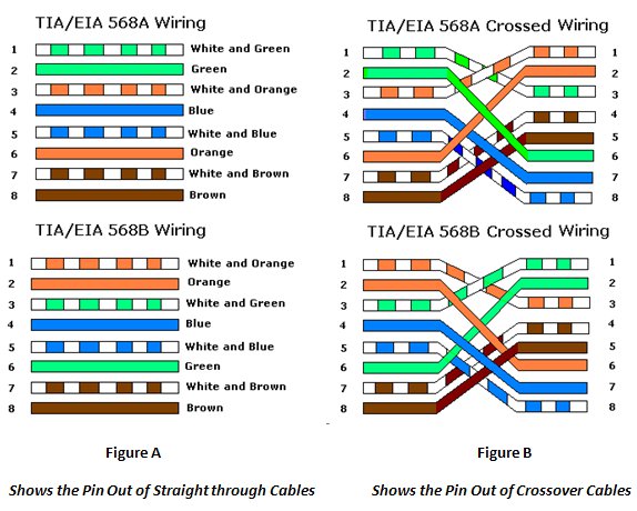
The objective of this project was to build a device capable of checking the correct correspondence of the pins in an RJ45 network cable according to the T-568-B standard for straight-through and crossover wiring configurations.
Ingredients
To develop this project, I used the following materials:
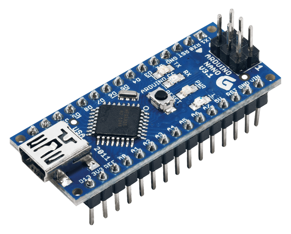
- Arduino Nano,
- Gray 3D printer filament,
- LCD Display 16x4,
- LCD to I²C adapter,
- USB mini Cable,
- DuPont cables,
- RJ45 connector (x2),
- RJ45 coupler (x2),
- Some network cables for testing,
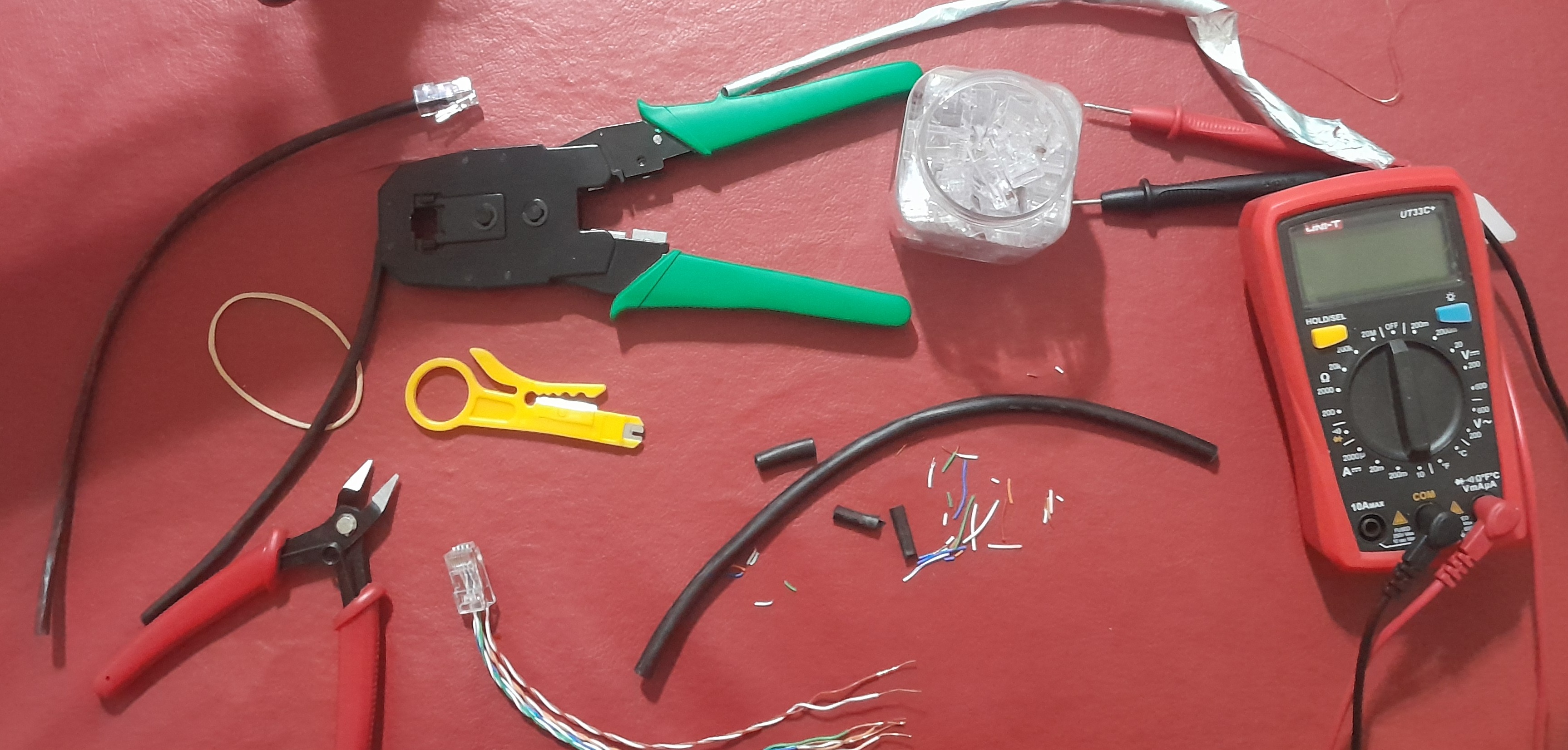
…and the following tools:
- Crimping tool,
- Cutting pliers,
- Soldering iron,
- 3D printer,
- A PC with Arduino IDE installed.
Design and operation
Components
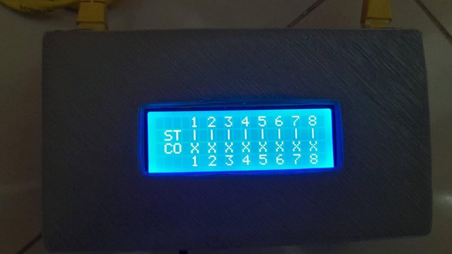
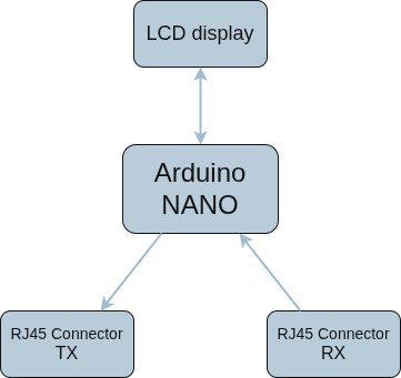
A RJ-45 connector’s wiring is checked for compliance with the appropriate connection standard (e.g., T-568-A or T-568-B) by sequentially comparing the continuity between the pin pairs at the ends. The result is displayed on an LCD display for both Crossover and Straight-Through wiring configurations.
An Arduino Nano was used to perform this process, allowing the necessary operations to be performed in a small space. It was also programmed in the Arduino language.
As for the electronic components, the LCD display has a module that simplifies the wiring and soldering so that the Arduino Nano can communicate simply using a library via I²C specific to this device.
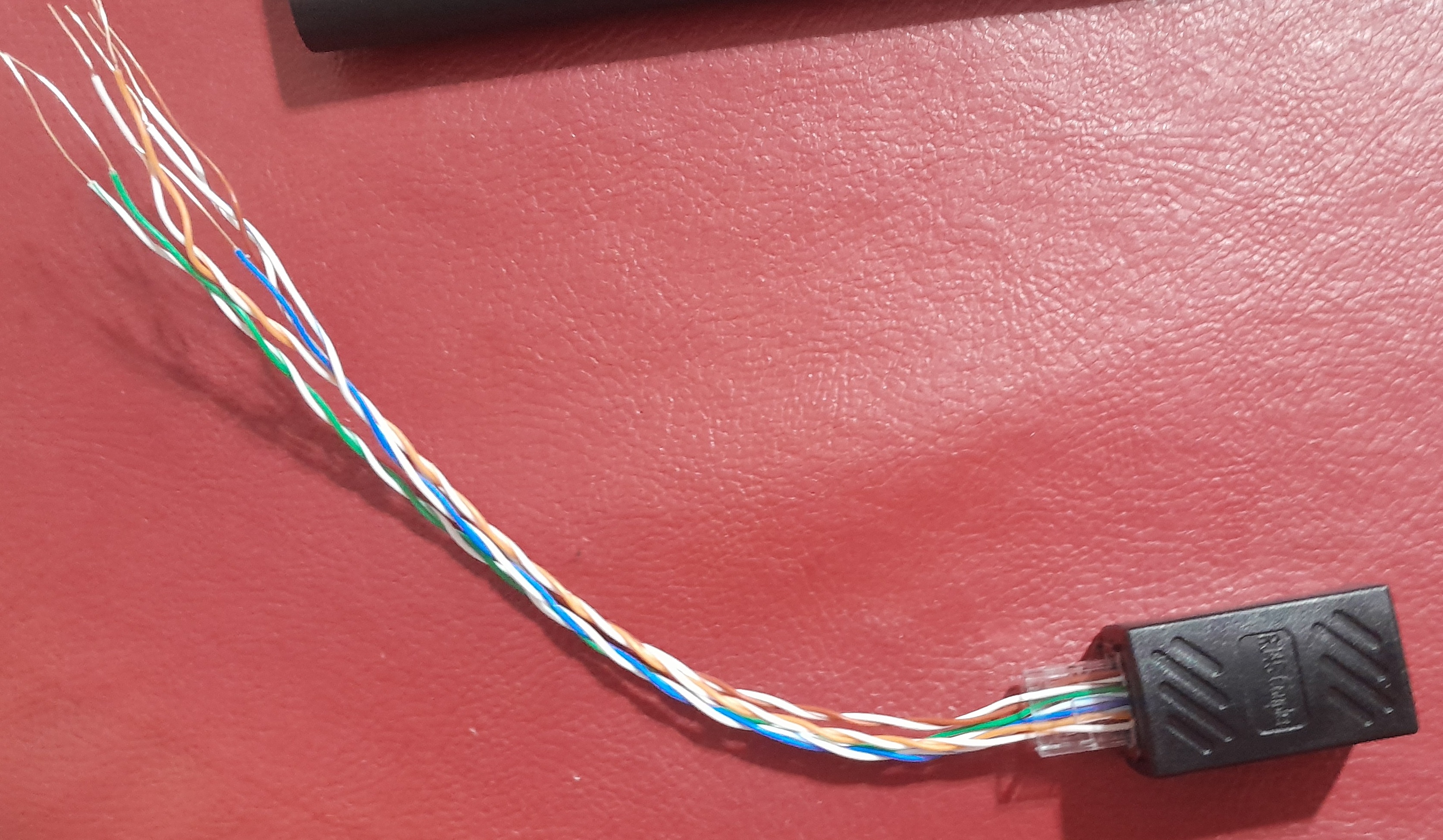
The cables to be tested connect to two RJ45 couplers on the outside of the device. Inside, there are two RJ45 connectors permanently connected to each coupler, whose wires are soldered onto the Arduino Nano.
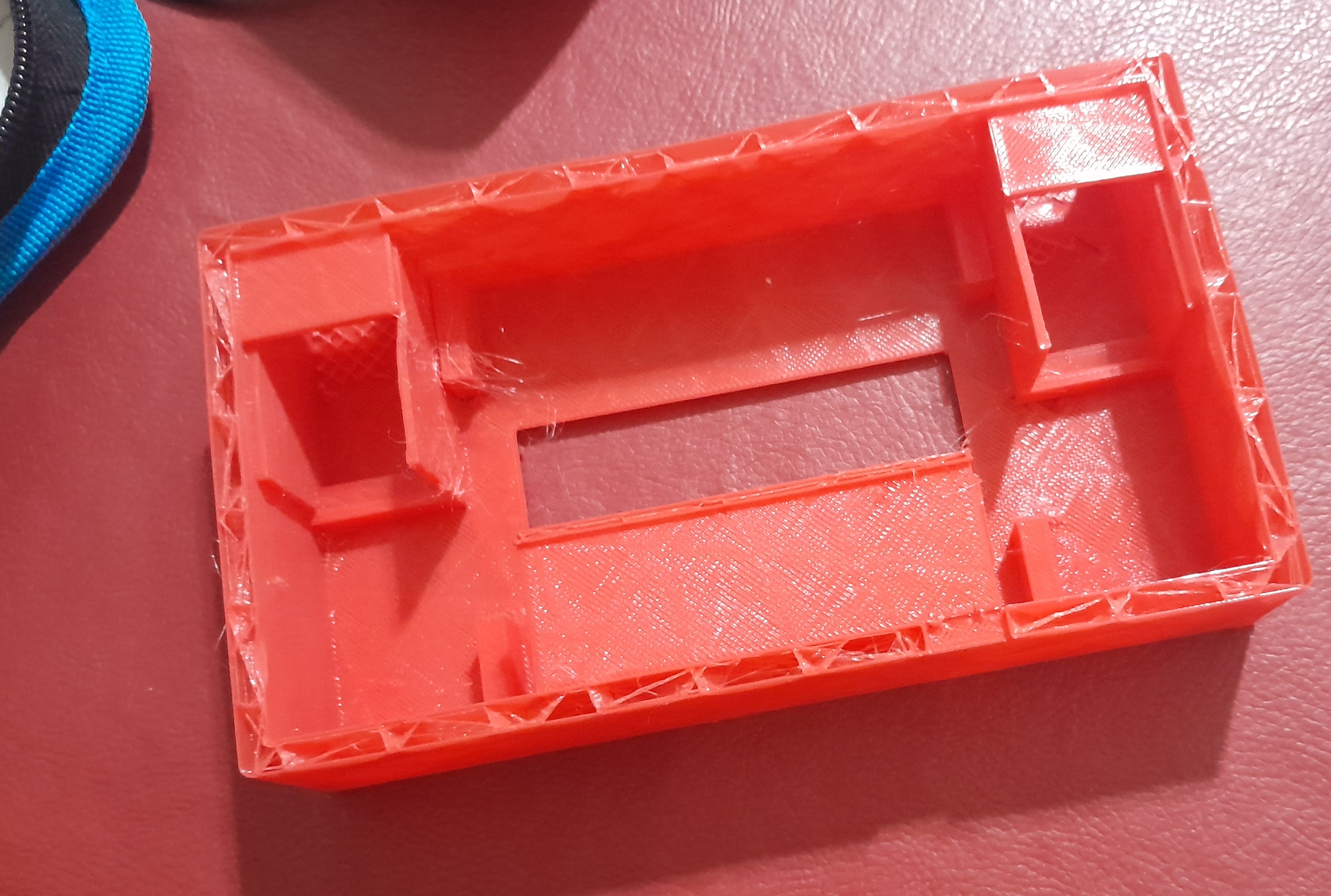
Finally, a USB cable was soldered to power the microcontroller. A case specifically designed for this project was also printed using a 3D printer.
Code
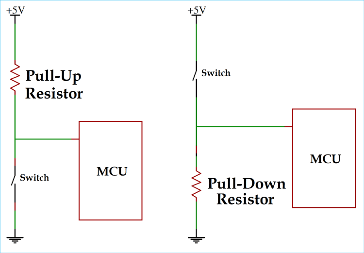
The Arduino input pins are configured as INPUT_PULLUP which makes it unnecessary to use pulldown resistors at the expense of processing 0 as a high value and 1 as a low value.
At the beginning of the code I declare the pins I will be using and create the lcd object.
#define PinC1_1 8
#define PinC1_2 17
#define PinC1_3 2
...

#define PinC2_1 16
#define PinC2_2 9
#define PinC2_3 10
...

LiquidCrystal_I2C lcd(0x27,20,4);
I then generate two pin arrays. One corresponding to the output pins and the other corresponding to the input pins.
const int CO[] = {PinC1_1, PinC1_2, PinC1_3, PinC1_4, PinC1_5, PinC1_6, PinC1_7, PinC1_8};
const int CI[] = {PinC2_1, PinC2_2, PinC2_3, PinC2_4, PinC2_5, PinC2_6, PinC2_7, PinC2_8};
I also then generate the matrices that indicate the correspondence between pins.
const int StraightThrough[][2] = {
  {PinC1_1, PinC2_1},
  {PinC1_2, PinC2_2},
  {PinC1_3, PinC2_3},
  {PinC1_4, PinC2_4},
  {PinC1_5, PinC2_5},
  {PinC1_6, PinC2_6},
  {PinC1_7, PinC2_7},
  {PinC1_8, PinC2_8}
};

const int CrossOver[][2] = {
  {PinC1_1, PinC2_3},
  {PinC1_2, PinC2_6},
  {PinC1_3, PinC2_1},
  {PinC1_4, PinC2_7},
  {PinC1_5, PinC2_8},
  {PinC1_6, PinC2_2},
  {PinC1_7, PinC2_4},
  {PinC1_8, PinC2_5}
};
I have created several functions that allow me to encapsulate program behaviors that are very important:
- Set all selected pins to high (0)
- Set all selected pins to low (1)
- Set all selected pins as input
- Set all selected pins as output
A very important function is detectCable(), as it lets us know if the user has connected a network cable to the device. It will return a bool depending on what was detected.
bool detectCable(){
setAllHigh(CO);
for(int i=0; i < 8; i++){
if (digitalRead(CI[i]) == HIGH_PullUp){
return true;
}
delay(10);
}
return false;
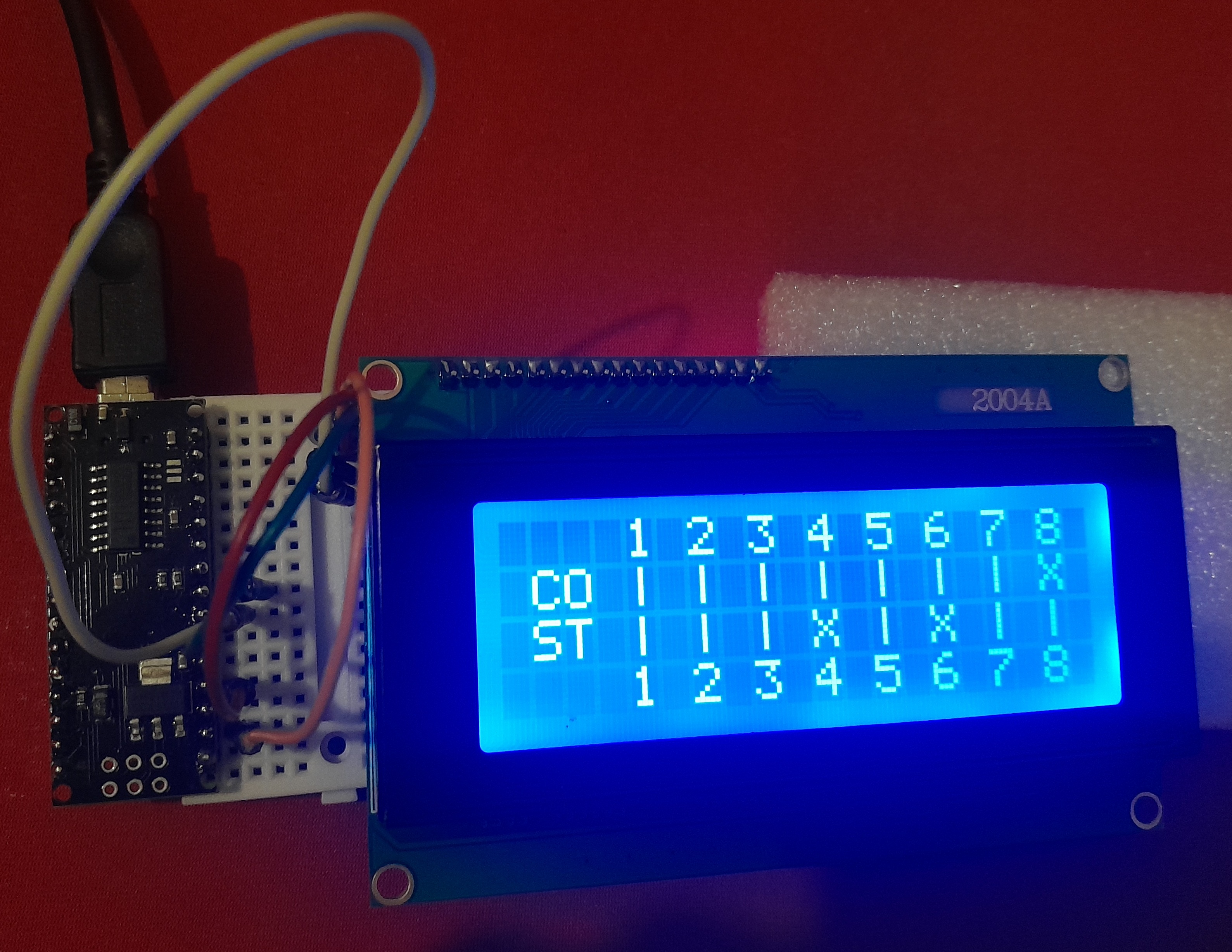
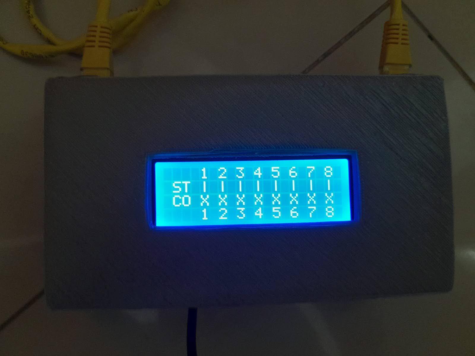
}Perhaps the most important function here is comparePins(). It detects pin correspondence based on the array passed to it as a parameter. Depending on what it finds, it displays | if the connection is valid and X if it isn’t.
void comparePins(int S[][2]){
  // set every output pin to low
  setAllLow(CO);

  // loop parameter
  for (int i=0; i < 8; i++){

    // set pin to 1
    setBitIO(S[i][0], HIGH_PullUp);

    if (digitalRead(S[i][1]) == HIGH_PullUp){
      // link is correct

      lcd.print("| ");
      delay(50);
    } else{
      // link is incorrect

      Serial.print(S[i][0]);
      Serial.print("-->");
      Serial.println(S[i][1]);
      lcd.print("X ");
      delay(50);
    }

    // set pin back to 0
    setBitIO(S[i][0], LOW_PullUp);
  }
}
In void setup() we simply initialize the LCD display and set certain pins as output and others as input.
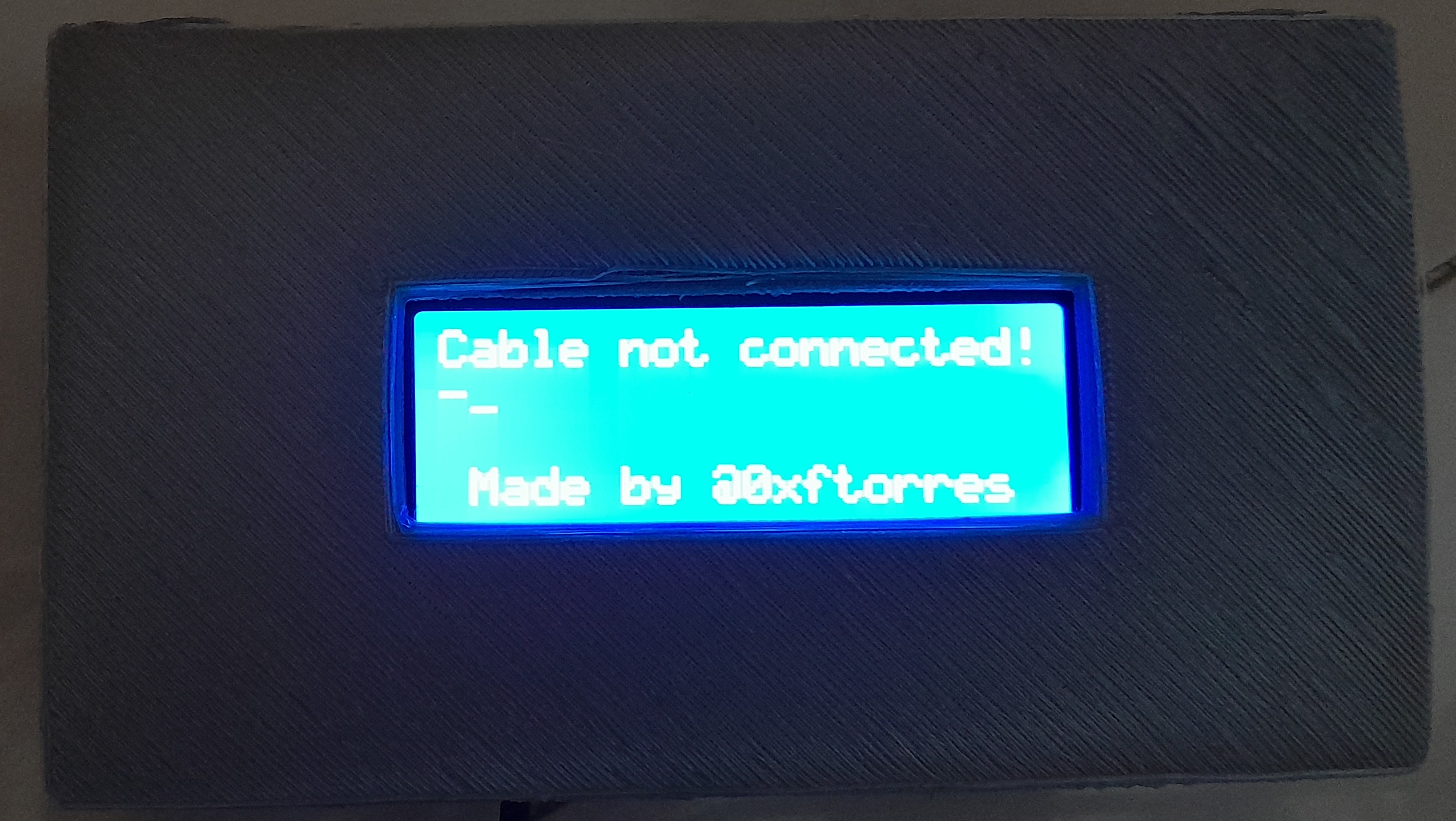
Finally, in the void loop(), we call detectCable() at each recursion. If it returns true (which means that a network cable has been detected), then the base grid is printed on the display and the pin comparisons begin. If it returns false (which means that no network cable was detected), a loading screen is displayed, waiting for the user to plug in the cable. In either case, the program waits 10 seconds and then returns to the beginning of the void loop(), which repeats all of the above until the device is turned off.
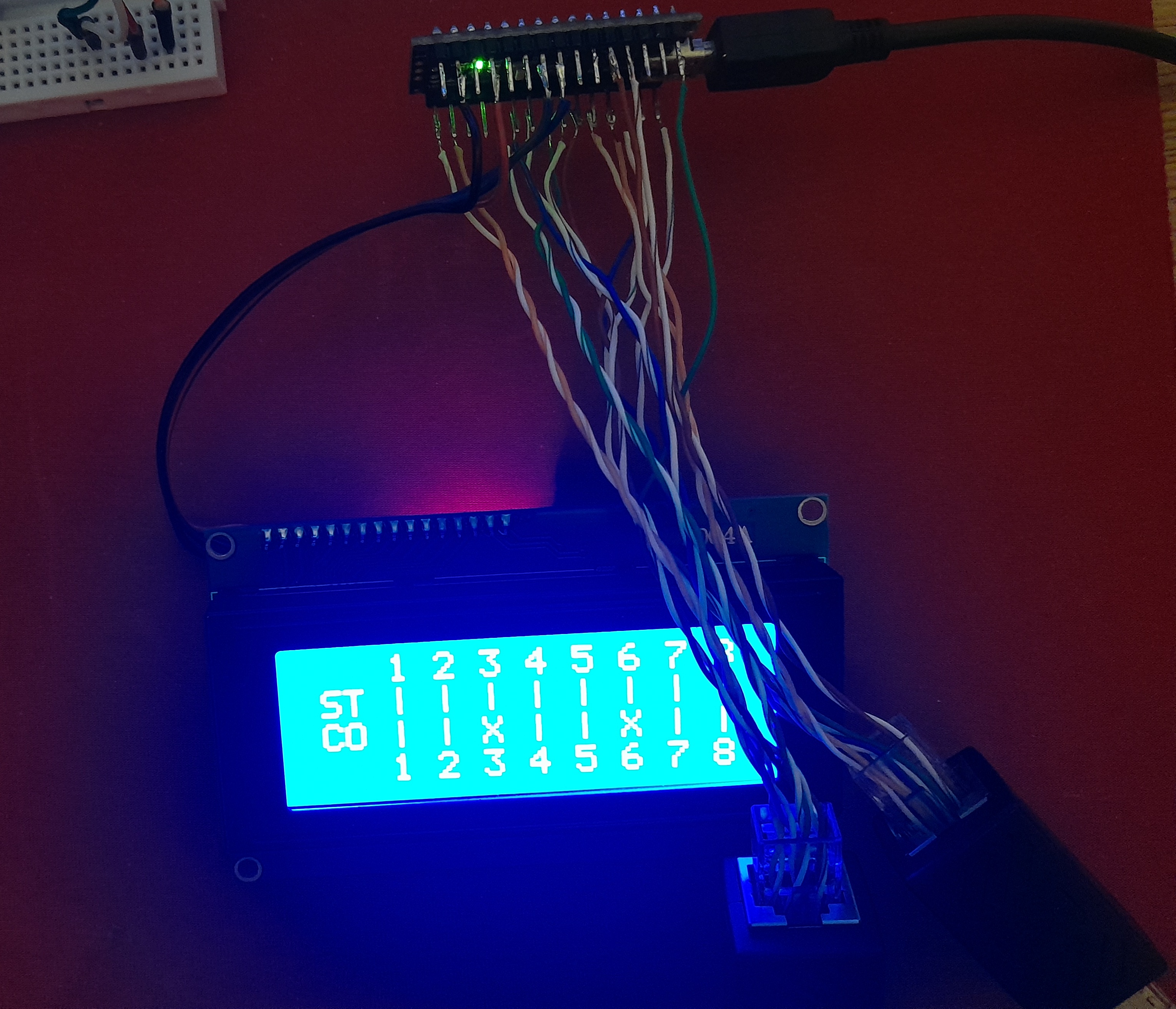
The program was tested on a mini-breadboard, using DuPont wires, and then permanently soldered with tin. The source code is on my github if you’d like to check it out.
Results
The full project was tested with straight-through and crossover T-568-B cables, and the expected results were achieved. The project was also tested with improperly made cables as an example, and the results were also as expected.
The case where the components are in had to be manually modified after 3D printing because certain measurements didn’t turn out as expected, and the material bent more than expected. I made several printed models with lower density to test the layout of the electronic components. It’s worth noting that the solder on the wires often broke, making it very difficult to ensure contact between the microcontroller pins.
Throughout the project, various problems arose. For example, since no cables were connected, the inputs indicated random values. The solution I found to this was to solder pulldown resistors to ground or use the pullup resistor integrated into the Arduino Nano board. I decided to do the latter, since it allowed me to save time, resources, and space inside the case. Later, I discovered that some input pins did not show the expected results when configured as INPUT_PULLUP, but did when configured as INPUT. The solution to this was to change those pins to OUTPUT and the other related pin to INPUT_PULLUP, through the DEFINE at the top of the program.
Conclusion and what I’ve learned
This project provides me with a very useful tool in the field of Network Engineering, as it is used every time a new network cable is made or tested. I learned about high-impedance pin states, when to use a pull-up resistor and when to use a pull-down resistor, and I also improved my knowledge of the T-568-A and T-568-B straight-through and crossover standards, which I hadn’t previously learned.
Future improvements to the project:
- A battery, so it doesn’t depend on a power source;
- An on/off button, to complement the previous point;
- A short-circuit alert, to detect if a cable is cut.